Home › Robotics Lab › Line Follower
Line follower robot simulator: build, wire and code it in 3D
Get a robot round its first track before you buy a single sensor.
Build a line follower robot from its parts, wire two IR sensors and an L298N motor driver to an Arduino Uno, and run the code in 3D. Change the speeds and watch it hold the track, or lose it.
Free with a free account · Runs in the browser · Class 8 to 10
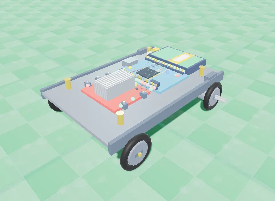
The classic first robot, without the kit
Every student builds the robot most robotics courses start with, at the same time, in the browser.
See why it leaves the track
Change one speed, run it again and watch the difference. Tuning becomes something you see, not guess.
Code that runs on a real one
Same pins, same L298N, same logic: take the sketch to a real line follower when you build it.
How the line follower works
Two IR sensors sit under the front of the robot, one on each side of a black line. Each reads 0 on the black line and 1 on the white floor. The Arduino reads both and drives the two wheels at different speeds to steer:
| Left sensor | Right sensor | What it means | What the robot does |
|---|---|---|---|
| On the line (0) | On the line (0) | Centred on the track | Both wheels at LINE_SPEED: straight ahead |
| On the line (0) | Off (1) | It drifted right | Turn left: left wheel slow, right wheel fast |
| Off (1) | On the line (0) | It drifted left | Turn right: left wheel fast, right wheel slow |
| Off (1) | Off (1) | Lost the line | Stop |
Parts you build it from
Arduino Uno
The microcontroller that reads the sensors and runs your code.
L298N motor driver
A dual H-bridge that lets the Arduino set each motor's speed and direction.
Two IR sensors
The robot's two "eyes" on the floor, left and right of the line.
Two DC motors and a 4-wheel chassis
One motor drives the left side, one the right: steering is a difference in speed.
7.4 V LiPo battery
Powers the motor driver; its ground is shared with the Arduino.
Wiring
These are the connections the lab checks before it lets the line follower run.
| From | To |
|---|---|
| Battery (+) | L298N VCC |
| Battery (−) | L298N GND |
| Arduino GND | L298N GND |
| Arduino D3 | L298N IN1 (left motor forward) |
| Arduino D4 | L298N IN2 (left motor reverse) |
| Arduino D5 | L298N IN3 (right motor forward) |
| Arduino D6 | L298N IN4 (right motor reverse) |
| L298N OUT1 / OUT2 | Left motor (+ / −) |
| L298N OUT3 / OUT4 | Right motor (+ / −) |
| Arduino 5V / GND | IR left VCC / GND |
| Arduino D2 | IR left OUT |
| Arduino 5V / GND | IR right VCC / GND |
| Arduino D7 | IR right OUT |
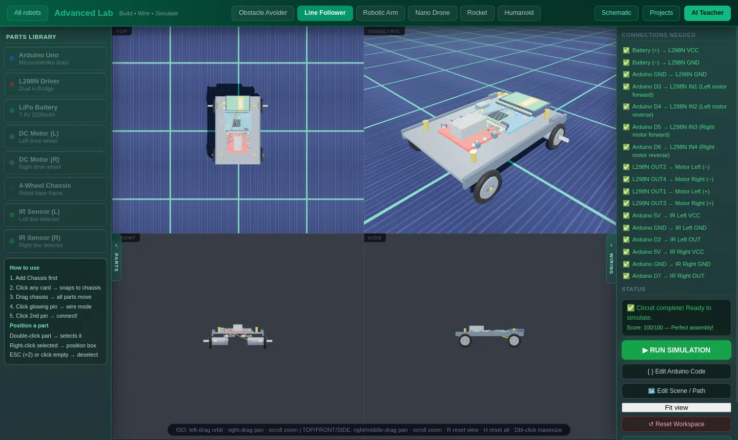
The code
This is the code the lab starts with. Three values decide how it drives: LINE_SPEED (straight), TURN_SPEED (the outer wheel in a turn) and BASE_SPEED (the inner wheel). With BASE_SPEED at 0 it pivots and jerks; around 70 to 80 it curves smoothly.
// --- PIN DEFINITIONS (must match your wiring!) ---
#define IR_LEFT   2   // IR Left sensor OUT  -> Arduino D2
#define IR_RIGHT  7   // IR Right sensor OUT -> Arduino D7
#define IN1  3        // L298N IN1 -> D3  (Left motor forward)
#define IN2  4        // L298N IN2 -> D4  (Left motor reverse)
#define IN3  5        // L298N IN3 -> D5  (Right motor forward)
#define IN4  6        // L298N IN4 -> D6  (Right motor reverse)

// -- TUNE THESE THREE VALUES --
#define LINE_SPEED  130   // Straight speed   (0-255)
#define TURN_SPEED  230   // Outer wheel speed during turn  (0-255)
#define BASE_SPEED   70   // Inner wheel speed during turn  (0-255)
// Rule: TURN_SPEED > LINE_SPEED > BASE_SPEED  for best tracking

void moveForward() {
  analogWrite(IN1,LINE_SPEED); digitalWrite(IN2,LOW);
  analogWrite(IN3,LINE_SPEED); digitalWrite(IN4,LOW);
}
void turnLeft() {   // Right wheel faster -> robot curves left
  analogWrite(IN1,BASE_SPEED); digitalWrite(IN2,LOW);
  analogWrite(IN3,TURN_SPEED); digitalWrite(IN4,LOW);
}
void turnRight() {  // Left wheel faster -> robot curves right
  analogWrite(IN1,TURN_SPEED); digitalWrite(IN2,LOW);
  analogWrite(IN3,BASE_SPEED); digitalWrite(IN4,LOW);
}
void stopMotors() {
  digitalWrite(IN1,LOW); digitalWrite(IN2,LOW);
  digitalWrite(IN3,LOW); digitalWrite(IN4,LOW);
}

void setup() {
  pinMode(IR_LEFT,INPUT); pinMode(IR_RIGHT,INPUT);
  pinMode(IN1,OUTPUT); pinMode(IN2,OUTPUT);
  pinMode(IN3,OUTPUT); pinMode(IN4,OUTPUT);
}

void loop() {
  // 0 = on BLACK line, 1 = on WHITE floor
  int left  = digitalRead(IR_LEFT);
  int right = digitalRead(IR_RIGHT);

  if (!left && !right) {        // both on line -> go straight
    moveForward();
  } else if (!left && right) {  // left on line, right off -> drifted right
    turnLeft();
  } else if (left && !right) {  // right on line, left off -> drifted left
    turnRight();
  } else {                      // both off line -> lost track
    stopMotors();
  }
}
Code it with blocks first
In the lab's coding room the same robot is programmed with blocks: if BOTH eyes are on the line, if the LEFT eye is on the line, set the wheels — left 60 % right 60 %, hold it for 0.2 seconds. Students get it round the track with blocks, then open the Arduino code to see the same logic in C++.
Try this in the lab
- Run it with the default values and watch it follow the circle.
- Set
BASE_SPEEDto 0. Why does the turn become a jerk? - Set
BASE_SPEEDequal toLINE_SPEED. Why does it stop turning at all? - Raise
LINE_SPEEDuntil it loses the line, then fix it without lowering it.
Line Follower: common questions
How does a line follower robot work?
Two IR sensors under the front of the robot look at the floor. On the black line a sensor reads 0, on the white floor it reads 1. If the robot drifts right, the left sensor stays on the line, so the code slows the left wheel and speeds up the right one to steer back. If both sensors lose the line, it stops.
Which sensors does a line follower use?
Two IR (infrared) reflectance sensors, one on each side of the line. White reflects more infrared light than black, so each sensor tells the Arduino whether it is over the line or the floor.
What parts do I need to build one?
An Arduino Uno, an L298N dual H-bridge motor driver, two DC motors with wheels, a chassis, two IR sensors and a 7.4 V battery. The simulator has the same parts, so you can build and test it before buying them.
Why does my line follower lose the line?
Usually it is going too fast for its corrections. Lower LINE_SPEED, keep TURN_SPEED high and set BASE_SPEED above 0 so it curves instead of jerking. In the code, keep TURN_SPEED greater than LINE_SPEED, and LINE_SPEED greater than BASE_SPEED.
Can I use this code on a real robot?
Yes, with the same wiring. Before you flash it, keep the ENA and ENB jumpers on the L298N module (without them the wheels will not turn) and join the battery ground to an Arduino GND.
Is the line follower simulator free?
Yes. The Line Follower is free with a free SPYRAL account, including its coding room and the advanced lab where you wire it and edit the Arduino code.
Other robots in the lab
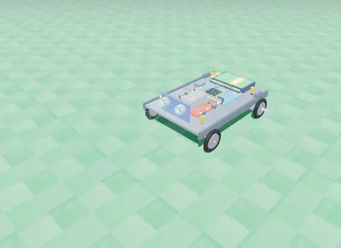
Obstacle Avoider
An ultrasonic sensor measures the distance ahead; an L298N driver and your code make it turn away from walls.
Obstacle Avoider
Robotic Arm
Three servo joints and a gripper: program a pick-and-place sequence and work out where the hand goes from two angles.
Robotic Arm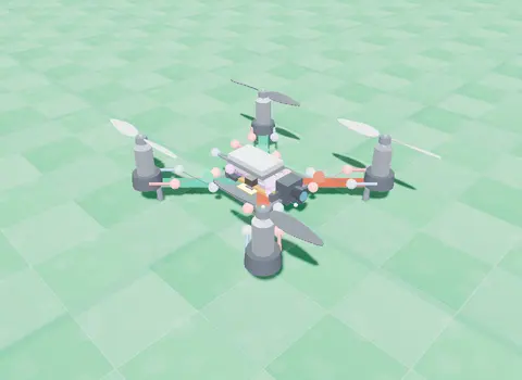
Nano Drone
A small quadcopter: learn lift and thrust, then take off, turn, hover and land with blocks you write.
Open the Nano Drone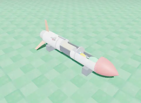
Rocket
Stack the stages and a flight computer, then code ignition, staging, the top of the flight and the parachute.
Rocket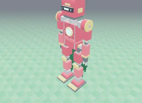
Humanoid
A servo-driven walking robot with real torque limits and friction: tune its balance until it walks.
HumanoidRead more: tuning a line follower · line follower simulation for STEM classes
Build the line follower today. No kit, no installs.